


By Brian Dean
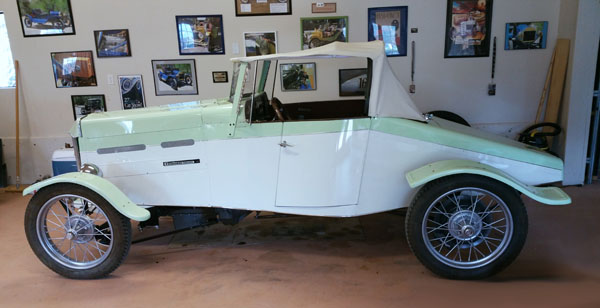
So, you have a Model T that you want to personalize? Join the thousands of T owners that have created their own distinctive car by turning it into a Model T speedster. Back in the day, when automotive journalism was a nascent art, editors sent their writers into the wilds of America looking for undiscovered speedsters. Everyone knew what a factory produced T looked like but every speedster incited interest because it was different, sometimes in subtle ways and often radically different. Some owners wanted to improve the stock T to suit their particular use but almost all of them wanted to go faster, beat their neighbors off the starting line and in some cases enter and win races. Primary modifications meant reducing the weight of the car and increasing horsepower. Soon, modifying a car to make a distinctive style statement created a new industry of aftermarket parts and accessories. By the mid 1920’s, hundreds of companies had been created to sell performance and style parts for the Model T Ford. A very serious industry had grown up around auto racing and the Model T was right in the thick of it.
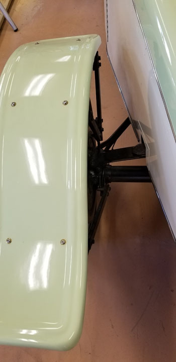
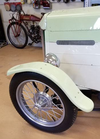
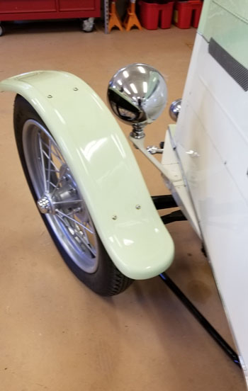
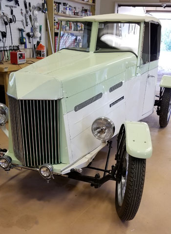
Let’s suppose that you want to further personalize your T speedster by installing distinctive fenders…cycle fenders. Cycle fenders are characterized by mounting to the axles of the car instead of the body. Since they don’t move up and down with the car body, they can be mounted close to the circumference of the tires and are usually lighter in weight and smaller than stock fenders in length and width. Their other unique characteristic is that the front fenders steer with the front wheels. The visual impact of fenders “floating” above the tires, unattached to the car body, and steering with the wheels is a compelling sight. This primer will describe my hard-earned lessons of what not to do and offer the solutions that should allow you to design and create cycle fenders for your T, regardless of age, body style or accessory brake systems.
Your first job is to select the style, size and material of your new fenders. There are so many choices of motorcycle, trailer, ATV, and car fenders on-line that you can become overwhelmed by the variety. Potentially, many of these could be adapted to your T. Since I had built my speedster body entirely of aluminum, that material was my first choice. Two weeks of frustrating research said that none of the available fenders was to my liking to say nothing of the cost. But wait, I have an English wheel, I’ve already built the car body, why not form my own fenders? The answer is that you need many years of experience with metal forming tools, especially involving an English wheel making compound curves, to successfully make fenders. I managed to destroy a few hundred dollars of aluminum sheet before rethinking this project. Skip forward to an evening when I was pawing through one of many parts catalogs and discovered that Speedway, Inc. of Lincoln, Nebraska had a variety of fiberglass “Model T” fenders.
https://www.speedwaymotors.com/Search?Facet=GA_SuperMarket%3AStreet&query=model++t+fenders .
Unpainted, gel coat, light weight, designed for a T and reasonably priced. They had front and rear fenders in exactly the right style. I swallowed my pride and bought them.
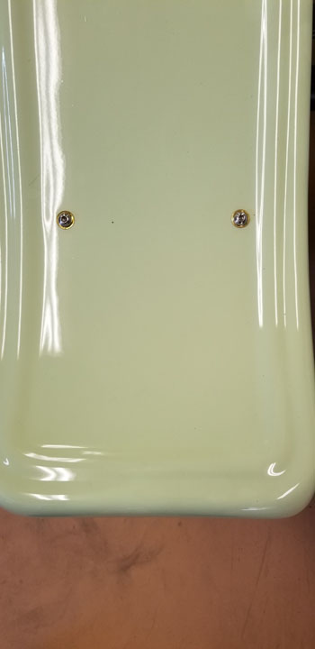
When the fenders arrived, I did a visual fit by setting each fender on its respective tire and centered the fender laterally on the tire tread. Moving each fender fore and aft on the tire gave a visual impression of the most pleasing position. It was necessary to measure the distance from the floor to the leading-edge lip and trailing edge lip of each fender and adjust the opposite side fender to match. Your next decision is how much clearance you want between the tire tread and the fender at the closest point. Since cycle fenders maintain a constant distance from the tire, they can be mounted much closer than body mount fenders. Using small blocks of wood of different thickness, I finally chose ¾ inch clearance at the top center, the closest point of proximity. Because my fenders are different shapes and widths between front and rear, it was necessary to work with each end of the car as a distinct project.
Engineering the mounts and mounting points was the next challenge. Having seen several cars with cycle fenders and watching them being driven, it appeared that nearly all of them flexed, vibrated or buzzed during motion. Owners also reported distressing mount failures. Most of these used steel rod or steel tube to support the fenders. All used two or three struts from a common plane on the axle or brake backing plate to the inner edge of the fender. This put the struts in a common front to rear 1-dimensional plane and did not control side-to-side vibration of the fender. The solution was to design the axle/backing plate lower mounts in a tripod configuration. The upper end of the fender struts would be in a common plane dictated by the inner edge of the fender but offsetting only one of the lower mounts would achieve the tripod.
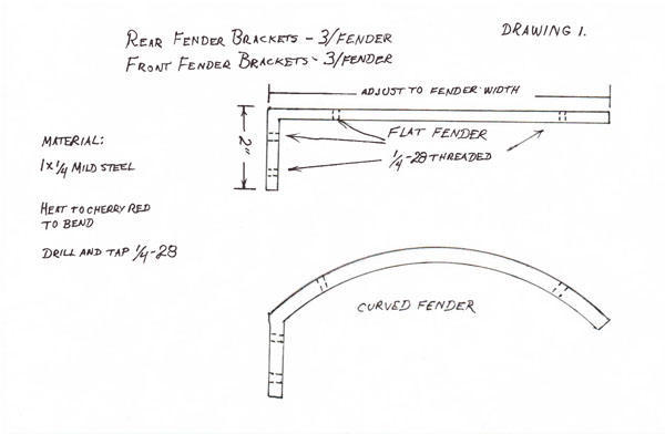
FENDER BRACKETS
The first items to manufacture were the fender brackets. These needed to be substantial enough that they would support the fender in position and provide a means to attach to the fender and then to the respective vertical strut. Each fender required 3 brackets. Your design of the fender brackets will depend upon the shape and the material of your fenders. My fiberglass fenders are flat across their width with a raised bead on each edge. This allowed a design of a simple “L” constructed from 1×1/4 mild steel bar. The rear wheel brackets are identical (6) and all of the front wheel brackets are identical (6). The fenders attach to the brackets by ¼-28 machine screws (stainless steel, of course, we don’t want no stinking rust) into holes drilled and tapped in the brackets. The screws are selected to be flush with the under- side of the brackets. Loc-Tite assures their security. See Drawing 1 for dimensions.
REAR FENDER MOUNTING
The axle flange where the radius rod mounts on the rear wheel axle offers a location forward of the axle for a single “Y” mount you will make of 1”x1/4” steel bar. The “Y” mount provides two of the three mounting points for the rear fender. See Drawing No. 2 for the rear wheel “Y” mount specs.
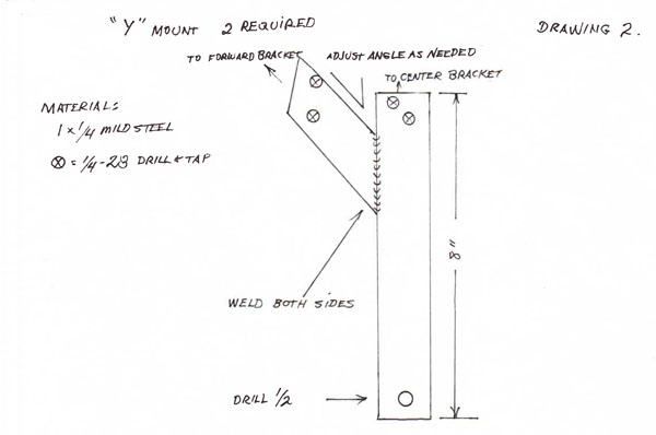
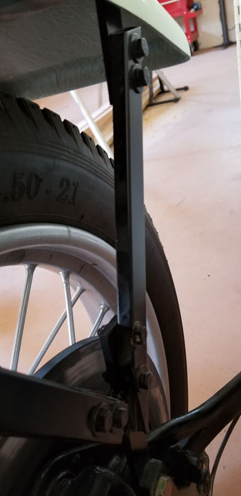
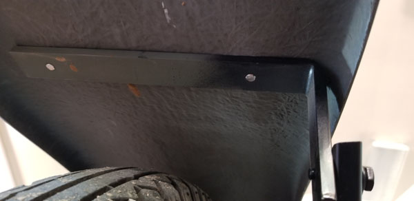
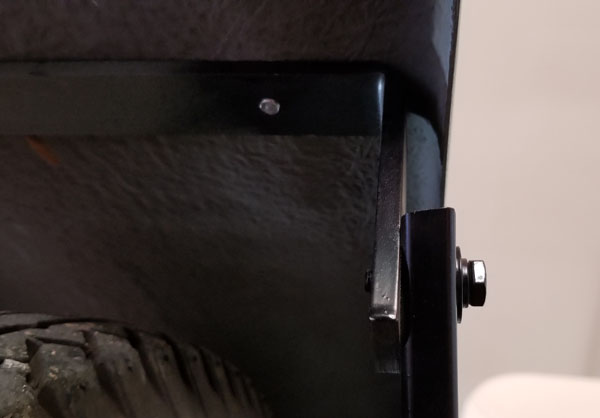
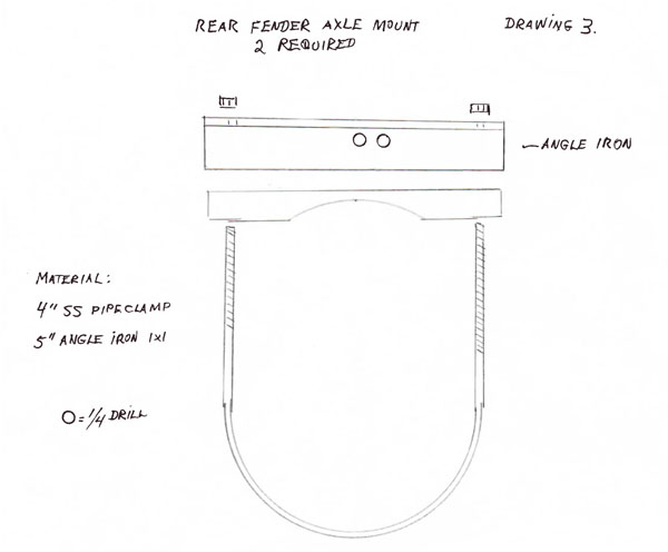
Make sure the “Y” mount bolts clear all brake parts inside the wheel and the external brakes, such as Rocky Mountain or Sure-Stop disc brakes, if installed. Attach the mount to the axle flange at the radius rod fork, upper mount hole with a ½-20 bolt and self-locking nut. This bolt will need to be at least ¼” longer than the original bolt. The third mount point is constructed using a 4” stainless steel pipe clamp around the rear axle collar. Notice that a piece of 1” angle iron is used to make a mounting surface for the rear strut from the pipe clamp to the rear fender bracket. See Drawing 3 and photo of rear axle mount.
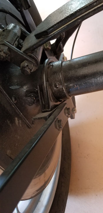
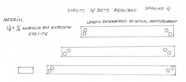
The struts from each mount to the respective fender bracket are made of 1.25”x 1/2” aluminum box extrusion, 6061-T6 grade. The aluminum is strong, stiff and corrosion resistant. When bolted between the base mounts and the fender brackets, it forms a simple and effective mounting system. See Drawing 4 and photo of rear fender axle mount.
When mounting a fender, it should be placed in the desired position on top of the tire and blocked or braced with shims to maintain the height, lateral position and longitudinal position. Be certain that your space measurement is from the center of the tire to underside of the closest fender bracket. You may need external bracing, maybe saw-horses, front and rear to assure alignment. Taping the fender to the bracing can be helpful. With shims in place between the fender and the tire, I suggest you wrap several turns of painter’s tape around the top of the fender and through the spokes of the wheel. Record all your measurements so that you can set up the opposite side the same way.
Plan your aluminum struts using a ruler or tape measure to find the length of each strut, one at a time. The angle of the fender brace extensions and the base mount extensions will not line up parallel to the strut. That is ok. Cut one strut to length. You need to position the strut so that it meets each fender bracket extension at a point that you can drill two ¼“ holes through the aluminum strut and into the fender bracket at each end. Having 6 small “C” clamps will make this much easier. You can clamp the three struts in place and position/reposition them before marking the struts for the holes. Remove the clamps (you did mark the struts fore, middle and aft, and an arrow pointing up, right?). Remove the struts, drill ¼” holes through both sides and clamp them back into place. Using a pointed Sharpie, mark the hole locations on the fender brackets and base mounts. Remove the fender brackets and base mounts, drill and tap the steel for ¼ – 28 x ¾ bolts. Reinstall the fender and base mount brackets, using a small flat washer under each bolt head. Do not torque anything at this point, you want only a friction fit so that you can make minor adjustments. Go get a cup of coffee. Feel better?
Let’s recheck the height and alignment of the fender. Small adjustments can be made by using the slack between the bolts and holes, or cutting a longer or shorter strut, or bending the Y brace in or out, rotating the Y brace on its single mounting hole, or by moving the “C” clamp on the axle collar. When the fender alignment looks right, tighten the Y brace mounting bolt, and the “C” clamp mounting nuts. Do the same thing to the other side of the car. Re-check for height, spacing and alignment from left and right sides of the car.

Notes: Drawings 1,2 and 3 show rear fender hardware.
Note: All bolt and nut hardware should be Grade 8.
FRONT FENDER MOUNTING
Model T’s didn’t come with front brakes, thence no front brake backing plates. The challenge is to find three points inboard of the front wheel that do not change their relationship to the plane of the wheel regardless of where it is steered. The first of these points is the top of the spindle bolt, the second is the spindle arm nut, and the third is the top of the tie rod bolt. Looking at these points, you can see that they form a natural triangle, which is just what we want for the base of a fender mount. We will need to manufacture three different items (x2) to create sturdy mounts for the front fenders. If you don’t have a machine lathe, milling machine and precision welding equipment in your shop, you can contract this work to a good machine shop.
Note: Drawings 4, (above) and 5,6 and 7 (below) illustrate the pieces to be manufactured.
If your front fenders are the same width as the rears, you already have the dimensions to make the fender brackets. If they are different, adjust the brackets and mounting holes accordingly. My rear fenders are 10” wide and the fronts are 7” wide. Regardless, the bracket tabs align with the inside edge of the fenders.
Remove the front wheels from the car. Remove the spindle bolts (king-pins). Mark them L or R for reinstallation. Remove the spindle arm nuts and put them in your spare parts collection. Note that when you removed the spindle arm nuts, the cotter pin was installed vertically through the arm. You are going to replace the nuts with new parts. Remove the tie rod bolts. Mark them L or R.
Let’s look at Drawing 5 and the photo for the replacement parts for the spindle arm nuts.
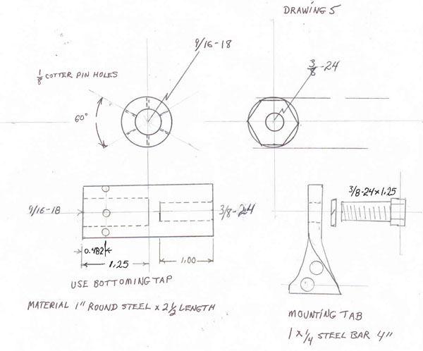
One part is the nut replacement. Notice that the new barrel nut is threaded in both ends. The pilot holes for the taps do not meet inside the nut.
The depth of the threads is important and both threaded holes are finished with a bottoming tap so that the useful threads go to the bottom of the pilot hole. The forward end of the barrel nut (3/8-24 hole) has 6 flats machined into the surface to support a 7/8” wrench. The rearward end of the barrel nut has 3 holes drilled completely through the nut at 60 degree angles to accommodate a 1/8 cotter pin. The cotter pin holes are set back from the end of the nut 31/64 (0.482) to align with the cotter pin hole in the spindle arm. When installing the barrel nut, tighten until the nut contacts the face of the spindle and then tighten to align the first cotter pin hole. Install 1/8 cotter pin.
The second part of the spindle arm nut replacement is a lower attachment point for the forward fender strut. This is made from a piece of 1×1/4 steel bar heated and twisted exactly 90 degrees. Attach this mounting tab to the barrel nut with a 3/8-24×1.25 bolt and lock washer.
SPINDLE BOLT POST
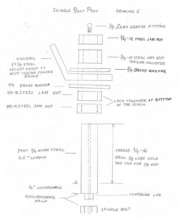
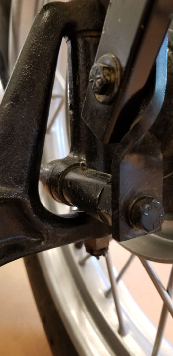
Drawing 6 shows the post and hardware that is to be added to the top of each spindle bolt. (See photos of spindle bolt post) First, remove the oiler from the spindle bolt. The post is turned from 3/4” round steel bar. When completed, the post must be precision welded into the top of the spindle bolt.
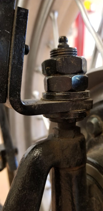
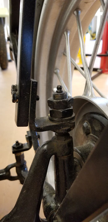
The spindle bolt is made from specially hardened steel and the welding technician must understand how to avoid drawing the temper from the spindle bolt or reharden the bolt. The post must be welded 360 degrees around the contact surfaces with the bolt to contain high pressure grease injected into the post from the Zerk fitting. The post serves as a pivot for the center fender strut. Note that the pivot bracket swivels between brass washers on the post. The ¾ nuts on the post, above and below the brass washers, should allow the pivot bracket to turn freely but not allow any vertical movement. In service, the spindle bolt does not turn with the spindle. The swivel piece moves between the two brass washers which act as bearings. Install the spindle bolt and stack the washers, swivel and nuts as shown in Drawing 6. Install a 1/8 Zerk fitting in the top of the spindle bolt post. You can avoid the aggravation and mess resulting from oil lubrication of the spindle post components and the rod bolt post components by lubricating the moving parts with a durable dry lubricant such as “Slip Plate No. 1”, a heavy duty dry film graphite lubricant. It also works wonders between the leaves of a leaf spring.
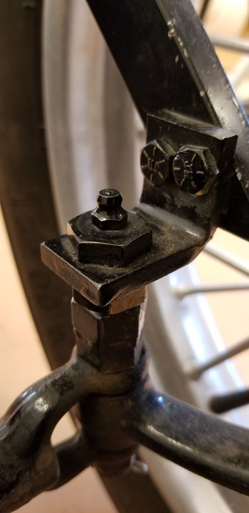
TIE ROD BOLT POST
Drawing 7, and the photo shows the post and hardware that is to be added to the top of the tie rod bolt. Remove the oiler from the bolt. Precision weld a thick ½-20 nut to the top of the bolt, assuring that the nut is centered and square with the bolt. Again, this is a hardened bolt and you must avoid drawing the temper or re-harden the bolt after welding.
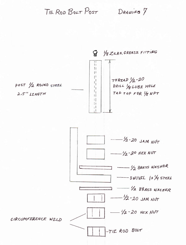
Machine a post bolt to the specifications of drawing 7. Stack the post bolt nuts, washers and swivel as shown. Screw the post bolt into the welded nut on the tie rod bolt until it bottoms, only finger tight. Hold the post bolt and tighten the lower jam nut. Lubricate the brass washers and tighten the upper hex nut to remove axial play in the stacked components. The swivel should rotate freely with no vertical movement. Hold the upper hex nut and tighten the upper jam nut. Install the tie rod bolt. Install a 1/8 Zerk fitting in the top of the rod bolt post.
FRONT WHEEL FENDER STRUTS
Check your front fender position for center on the tire and height above the tire (height is measured from the highest point of the tire to the closest fender bracket). Plan your struts to allow at least ¼ “ side clearance from the tire. This may require that one or both ends of the strut be mounted outside of the bracket/swivel tabs.
FIT AND FINISH
Check your work by fender center on tire; height above a level floor, front and rear; fore and aft alignment with the car centerline; and your satisfaction with the appearance. If you paint your mounting hardware black, it will help it to visually disappear.
TECH HELP
Questions, comments or improvements to this design are always welcome.
Contact us at: malpais25@msn.com Brian Dean, Tin Lizzies of Albuquerque.